>>>Mockup<<<
1Mechanical Structure Mockup
With the arrival of the motors, wheels, mounting brackets and hubs, the mechanical construction can begin.Guiding principle for the construction is the MVP strategy, in which a minimal working version, a vertical slice is built first. Functionalities are added as testing of more basic functionalities is successful.
Objective is to build the minimal structure that demonstrate the mechanical layout of four independent traction wheel with the intended form factor to comply with the Pi Wars 2020 specifications.
2Specifications
Maximum Footprint Width x Length x Height- 225mm x 300mm x 370mm Core platform
- 225mm x 400mm x 450mm With challenge specific attachments
- 325mm x 500mm x 450mm With extensible flaps
Illustration 1: PiWars Size Specifications
2.1Motor Block Components
Component chosen for the Motor Block are:
Illustration 2: OrangeBot Motor Block Components
Illustration 3: OrangeBot Motor Block Mechanical
Drawings
Both the Hub and the wheels needs to be modified to fit the motor
block.2.2Layout
OrangeBot is going to use four independent DC gearmotors with wheels. A central joint is going to allow the platform to swivel around the longitudinal axis of the robot.
Illustration 4: OrangeBot Motor Block Mechanical
Drawings
3Mechanical Construction
This section details the manufacturing steps for the mechanical construction.3.1Motor Block Assembly
First step is to modify the hub and the wheel to fit the motor block.The motor 6mm shaft already fits the 6mm hub hole.
The wheel must be modified to fit the hub. This requires enlarging the central hole to 12mm.
Video 1: Enlarge wheel hole to 12mm
Next step is to drill through both the hub imperial satellite holes and the wheel to create three M3.5 through hole to fix the wheel to the hub.
3.2Robot Base MVP
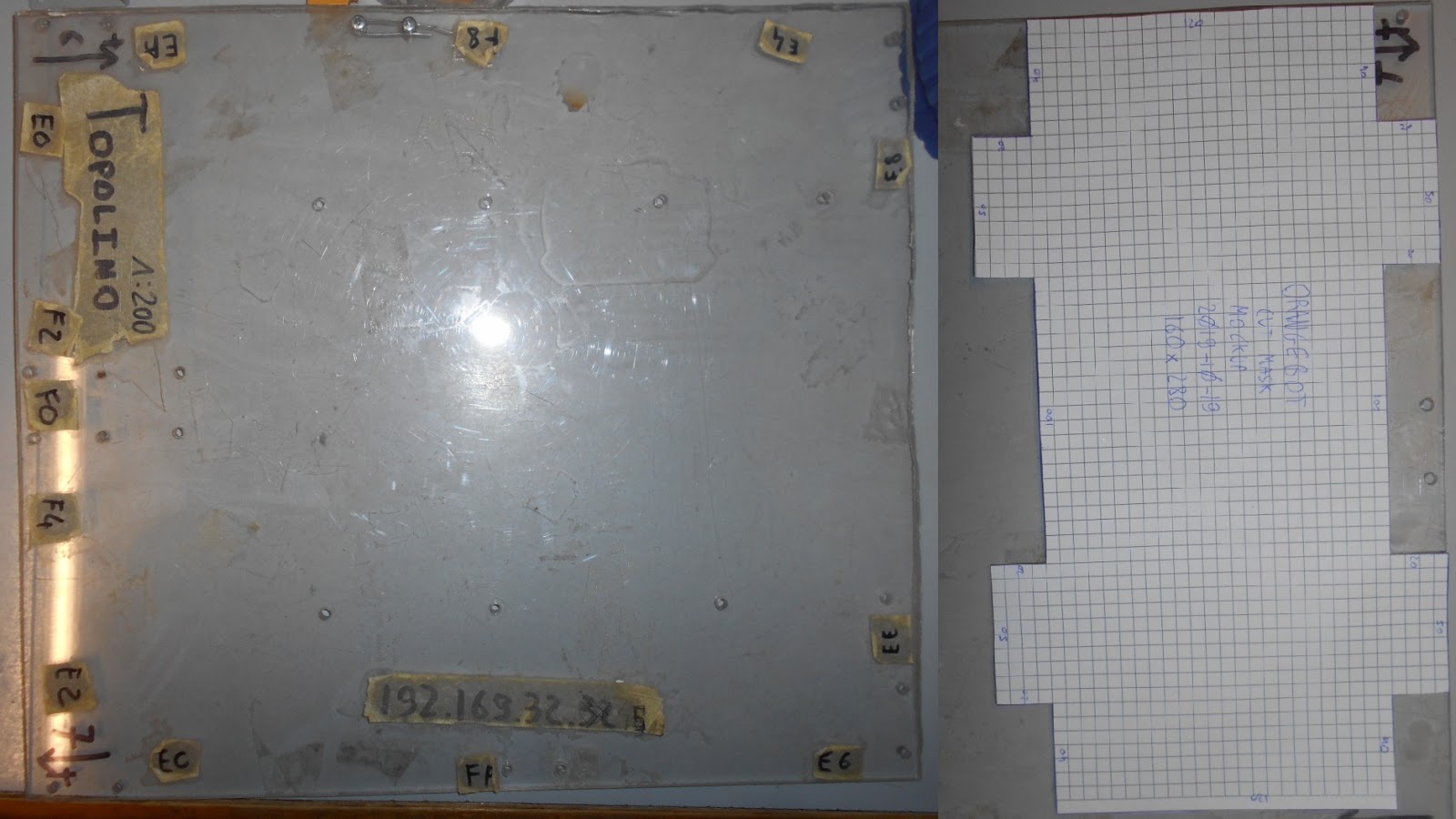
The minimal workable base is a simple slice of acrylic cut to shape and drilled to host the four motor block assemblies. This MVP is meant to demonstrate the traction and electronics and allow to get a feel for the size, in preparation for the next step of the mechanical assembly.3.2.1Cut Mask
First step is to design the cut mask to accommodate the four motor blocks. The encasing of the encoder of the gearmotors has been removed to save space and because the wirings of the gearmotors are going to be replaced altogether anyway.
Illustration 5: Base MVP Cut Mask
3.2.2Acrylic Sheet
For the sheet of acrylic,
the upper plate of our previous robot 'Topolino' was used. The cut
mask is kept in place by a few stripes of black tape.
Illustration 6: Acrylic
3.2.3Cut Acrylic Sheet
Illustration 7: Cut acrylic
3.2.4Acrylic Robot Base
Illustration 8: Acrylic Robot Base
3.3Motor Mounting Brackets
Now the mounting brackets can be assembled on the robot base.3.3.1Sanity Check Size
Check that motor block assemblies comply with the PiWars specifications with some margin.Margin is an healthy 30 x 20 mm.
Illustration 9: Check Size
3.3.2Place Motor Brackets
Mpounting brackets for the motor are placed precisely along guide lines and held in place.
Illustration 10: Place Brackets
3.3.3M3 Drills
M3 holes are drilled as precisely as possible. M3 bolts are used to keep the bracket in place as new holes are drilled.
Illustration 11: Drill acrylic sheet
3.3.4Clean Drills
Clean up the holes and apply M3 bolts to keep brackets in place.
Illustration 12: Countersink and clean up holes
3.3.5Assembly Bracket
The brackets are all assembled and aligned. Now the motors can be attached as well.
Illustration 13: Assembly Motor Brackets
3.4Assembly Motor Blocks
With the mounting brackets and the motors assembled, now the hub wheel assembly can proceed.
Illustration 14: Motors Assembled
3.5Assembly Wheels
Order of assembly:- Insert the M3 wheel screws in the hub (without the wheel)
- Insert the hub on the axle and tighten the hub-axle screws.
- Insert the wheel.
- Tighten the M3 bolt
Illustration 15: Wheel and Hub before and after
Drill
Illustration 16: Before and After Drill
It's very tricky to tighten the M3 screws on the wheel.4Skin Mockup
Cardboard plates were used to prototype the outer structure of the OrangeBot platform. M3x10 screws were used to bolt the plates together, resulting in a surprisingly solid and rigid structure.
Illustration 17: OrangeBot Mockup
The platform is modelled after an Armoured Personal Carrier or
APC. The platform is going to feature a fully operational turret,
tentatively equipped with an RC grade BB gun emplacement.
Tentatively, the turret is going to achieve full 360° turn
capabilities and +/-15° of azimuth. The camera is going to be
mounted on the gun emplacement for targeting and navigation.5Conclusions
This document detailed the development of the simplest possible vertical slice for the mechanical assembly.
Illustration 18: OrangeBot Mechanical MVP
ToDo list:- Thread the holes on the hub to M4 for ease of assembly
- Design a base to accommodate the longitudinal joint
- Design the turret and the chassis


No comments:
Post a Comment