2019-12-30

2019-12-30 Online Collision Calculator

>>> Online Collision Calculator<<<


Online tool to estimate the kinetic energy transferred by various weapon systems.
Used to evaluate the main weapon for OrangeBot.

2019-11-14

2019-11-03 OrangeBot Upgrade Motors


>>>Pi Wars 2020<<< 


1Motor Upgrade

The first assembly phase already revealed some issues with the motor block:
  1. Mounting of the wheel on the motor is needlessly fiddly
  2. With power electronic tested is time to add encoder and speed PID
With the successful completion of the first MVP phase (remote control of the platform from browser with open loop PWM motor control) it's time to disassemble the platform and begin the second construction phase.
Objective for this phase is to focus on the motor control. Add encoder decoding for each of the motor channel and add a speed PID. Since the motor blocks are to be disassembled, mounting of the wheels on the hub is to be upgraded as well.


1.1Upgrade Plan

Order of assembly is:
    1. Mount motor on its bracket
    2. Place M3 screws on the hub
    3. Mount the hub on the motor shaft and tighten two keys
    4. Insert the wheel on the hub
    5. Tighten the M3 screws by holding the butt of the screw with an L shaped clamp
The fifth step of the assembly is needlessly fiddly and has to be repeated for twelve screws.
Illustration 1: Current Motor Block Assembly
Upgrade plan is to:
  1. Remove step 2 of the old assembly phase
  2. Thread the small surviving holes M3
  3. Mount the wheel by bolting M3 screws of the right length from the front
  4. Add encoder connector and test encoder waveform


2Upgrade Hub

Thread the small surviving holes on the hub to accommodate M3 screws.
First disassemble the platform.
Illustration 2: Disassemble platform

Drill with 2.8 and thread the small holes on the hub M3
Illustration 3: Thread M3

Threading of twelve holes on four hubs complete.
Illustration 4: Hubs Threaded

Test full assembly. Use M3x16.
Illustration 5: Motor Block Assembly

Assembly looks good, and now the process is streamlined allowing for an easier maintenance of the platform.

2.1Order of Assembly

Order of assembly is:
  1. Mount motor on its bracket
  2. Mount the hub on the motor shaft and tighten two keys
  3. Mount the wheel on the hub using M3x16 screws
Thread on aluminium is not strong on the best of days, so care should be taken not to tighten too hard the screws. Use of a special anti-slide ring to the screw is advised.


3Encoders

An encoder connector is to be added to provide closed loop motor control.

3.1Connector

Holes needs to be prepared to add the connector by sucking away the tin.
Illustration 6: Prepare Holes

Connector chosen is a simple 2.54mm male pin strip
Illustration 7: Upgraded Motors

Power wires and soldered directly to the motor power pins to improve current capability.
Encoder uses four pins. Two for supply and two for channel A and B.


3.2Encoder Test

With the connectors taken care of, an encoder test was in order to verify the correct operation of the assembly and to verify the pin assignment.
Illustration 8: Encoder Test Circuit

The encoder is powered with 5V and returns two open drain outputs. Two 1K pull up resistors are used to bias the two channels. In the test circuit two sink LED are connected to the channels to visually inspect the encoder.


Video 1: Test Encoders Manually+12V motor in both directions


4Assembly

Assemble back the motors and the hub on the acrylic base.
Illustration 9: Re-Assembled Platform


5Proto Board Upgrade

Upgrade the main board to support four quadrature encoders.
Encoders are connected to PORTC of the microcontroller and are powered by the same 5V that powers the microcontroller itself.
Each encoder channel is equipped with a 1KOhm pull up resistor as the encoders of the IG32-05 motors are open drain.
Illustration 10: Proto Board Encoder Wirings


5.1Encoder Cables

Four encoder cables connects the proto board with the encoders mounted on the IG32-05 motors
Illustration 11: Make Encoder Cables
Wirings:
  • IG32-05 Side
    • Brown +5V
    • Black +0V
    • White CHA
    • Blue CHB
  • Proto Board Side
    • Black +0V
    • Brown +5V
    • White CHA
    • Blue CHB


6Conclusions

The scope of this upgrade has been to make the wheel mounting more convenient and to pave the way to add encoder feedback to the platform.
Illustration 12: Complete Wirings

Next step is to upgrade the firmware to read the encoder waveforms.


2019-11-07

2019-11-02 OrangeBot Remote Controls

>>>Pi Wars 2020<<< 


1Remote Controls

Up to this point “OrangeBot” has been built to have four motor blocks controlled in open loop by the proto board.
The scope of this week's upgrade is to move closer to the MVP by achieving
remote controls. This requires:
  • Serial communication and platform control messages
  • RaspberryPi powered and connected to the proto board
  • Raspberry Pi Remote Control OS Image


2Raspberry Pi

The architecture of the platform calls for a dual channel 5V3A power supply in which one of the channel is dedicated to the Raspberry Pi.
Currently, the TSP55386 evaluation board provides a 5V and a 3.3V channel, so the board needs to be modified to output two 5V channels like in the final configuration.

2.1Modify TPS55386 Evaluation Board

Starting from the schematics it can be seen that only one resistor needs to be upgraded. I skip modifying the compensation network.
Illustration 1 - TPS55386 Evaluation Board Schematics
There are several ways to do that. Either modify R10, or R12 or both.
Modifying R10 to the E12 resistor 3.9KOhm lead to a nice output voltage of 4.95V A bit on the low side but shouldn't be a problem since it's injected after the protections of the RPI saving some voltage drop there.


Upgrade is done by picking a 3.9KOhm resistor from a donor board and replacing R10.
Illustration 2 - Replace R10
With the resistor changed, a power test is conducted to verify the output of the regulator.
Illustration 3 - Test 5V output


2.2Raspberry Pi Adapter Connector

With the regulator taken care of, next step is to carry power and data to and from the GPIO.
Since hooking up to an RPI is an increasingly common task for me, an adapter was made to provide access to the power pins, the serial port and a generic GPIO pin for good measure that can be used to reset the proto board.
A switch has been added as well, to power up and down the RPI easily from the adapter.
Illustration 4 - RPI Adapter


2.3Raspberry Pi Power Test

A power test was conducted to verify that the RPI was powered correctly. The RPI adapter was then filled with hot glue to improve reliability. A label was added on top of the glue as cover and legend.
Illustration 5 - RPI Power Test


3Remote Controls

With the electronics of the RPI operational, next step was to flash a SD card with the OS image of the Remote Control stack developed for “Maze Runner” and “Seeker Of Ways - B”.
This >>>page<<< details the building of the OS Image.
Two actions were required to adapt the image to “OrangeBot”
  1. Change IP address
  2. Rename the host

3.1Change IP address

The starting image was in a different IP subnet mask that my home network. One option was to temporary connect a PC with the correct subnet to the RPI directly using a direct Ethernet cable, but because of laziness a screen and keyboard were plugged in to make the change directly rather than remotely.
Illustration 6 - RPI Power Test
New address is 192.168.1.4


3.2Change Host Name

Host name of the OS image was changed to the robot name: “OrangeBot”.
Illustration 7 - Host Name


4Serial Interface

With the Raspberry Pi fully operational, next step was to write the firmware for the UART interface between the proto board and the RPI and to complete the wirings.
Illustration 8 - Full Wirings


4.1Test Physical Interface

The firmware enables bidirectional communication at 256Kb/s. The AT4809 allows for a much more precise baud rate than the AT644 used previously. UART3 peripheral was allocated to the RPI communication channel.

>>>Serial interface NODE.JS application<<<

With the firmware written, waveforms were checked on both the RPI TX and AT4809 TX. The RPI was running test_serial.js, the same program used in the previous robots to test the serial interface.
Illustration 9 - Serial Waveforms


4.2Motor Parser Commands

With the serial interface up and running, next step was to add the >>>Uniparser V4<<< library and write commands to allow the RPI to control the motors in open loop.

>>>Ping command NODE.JS test application<<<

>>>Motor command NODE.JS test application<<<

Video 1 - Test Motor Messages
Currently implemented commands are:
  • “P” - Ping: Reset communication Timeout
  • “F” - Find: Return the signature of the board
  • "M%SPWM%S" - Motor: Set PWM of an individual motor
  • "PWMR%SL%S" - PWM: Set PWM of platform. Forward/Turn rate.


5Remote Controls

An upgrade was required to the firmware before proceeding with the full remote control test. A slew rate limiter was added to the firmware to protect the driver from sudden direction reversal.

>>>AT4809 Remote Control firmware repository on GitHub<<<

>>>NODE.JS Remote Control Software Stack<<<

With the upgrade in place, the remote control NODE.JS application could finally be tested.

Video 2 - Remote Control Full Test
Currently Implemented Features:
  • Parser Commands
  • Communication Timeout
  • Open loop PWM controls

5.1Roaming

As a final step, the electronic was mounted on a cardboard support and on the platform to let “OrangeBot” roam for the first time under remote controls from a web browser.
Illustration 10 - Pack Electronics
Illustration 11 - OrangeBot Assembled

Video 3 - OrangeBot Roams
In this test, driver operates in open loop limited to about 20% of PWM at 12V. This prevents the platform from turning because of the grip of the wheels.
In this test, “OrangeBot” is tethered with a 12V5A cable and an Ethernet cable.


6Conclusions

The Remote Control MVP was a complete success, resulting in “OrangeBot” roaming for the first time. Speed and power performance are amazing as expected. Platform responds immediately to button presses and acceleration/speed look very promising.
There are two major drawbacks that needs to be addressed next:
  • Wheel mounting is fiddly and unreliable
  • Open loop motor controls are not up to the tasks ahead of “OrangeBot”
A number of upgrades are required to proceed further and achieve an MVP that is PiWars worthy:
  • Mechanics: Upgrade wheel mounting on the Hub
  • Electronics: Wire the four quadrature encoders to the proto board. Wire all encoder connections on the back of the proto board.
  • Firmware: Write a quad channel encoder acquisition module. Add a quad PID speed controller
After the MVP is achieved, a number of upgrades are needed to get closer to the expected performance of the platform:
  • Mechanics: Structure with suspensions
  • Electronics: Design a custom PCB to collect all the electronics
  • Firmware: Twin loop current/speed PID controller
  • Software: Raspicam streaming module


2019-11-04

2019-10-27 OrangeBot Test Four Motors

>>>OrangeBot - Pi Wars 2020 Page<<<

>>>Prototype Board and Test Four Motors<<<


1Electronics

Previously an AT4809 with a VNH7040 combo has been tested in Option 1 configuration with the IG32-05 motors. Option 1 entails providing PWM on the VNH7040 PWM pin and using INA/SEL0 and INB for direction control and brake.

Illustration 1: Test AT4809 + VNH7040
Design is to be scaled up to four independent motors to prove the feasibility of “OrangeBot” design.


2VNH7040 Option 2 Configuration

Option 2 configuration consists in wiring the microcontroller PWM signal to INB in theory giving the remaining signals a more defined meaning like direction and enable.
This configuration has been tested to no avail. OPTION1 configuration is the way to go.


3AT4809 Pin Allocation

The first task is to allocate the pin function for the AT4809 microcontroller.
This has been an highly iterative process, involving preliminary PCB layout and allocation of resources of the microcontroller.
After much thinking, this is the version 4 of the allocation table for the pins.

Illustration 2: Pin Allocation Table V4


3.1VNH7040 PWM

The most obvious problem is the generation of four 20KHz PWM signals.
There are two options:
  1. Use the only timer type A TCA0 as six channel 8bit PWM generator
  2. Use all four timers type B TCB0 to TCB3 as 8bit PWM generator
Initially option 1 was chosen. Now because of other constraint, option 2 has been chosen. Relevant contiguous pins have been allocated to the VNH7040 PWM pin.

3.2VNH7040 SENSE

Four ADC pins have been dedicated to the four driver sense pin.
A pull down resistor will be required.
TODO: Test sense functionality.

3.3Encoder

Initially the hope was to use the four CCL LUTs combined with four timers type B to decode in hardware four quadrature encoders.
This is not possible because timers type B cannot be made to count external events.
As fall back, all encoder pins have been wired to the same port and an interrupt will be used to update all encoder counters on any edge event on any of the pins. There will be a limit on the frequency of the encoder channels that can be decoded.

3.4Servo

Current idea is to use a dual 5V3A buck generator and have four servo channels on the board. The timer type A can be used to generate the servo PPM modulated signals, so it has tentatively been assigned there. This can change.

3.5I/O

Remaining pins are generic software controlled I/Os and have been grouped in fast switching and slow switching. slow switching signals are wired to the pin banks that share the supply of the ADC as to limit noise injected somewhat.


4Prototype Board

To scale up the design to four motors, wirings have been moved to a prototyping board for reliability.

Illustration 3: Prototype Board Architecture
The architecture calls for a central board to host the AT4809 evaluation board with its onboard programmer disabled and an external connector for the UPDI programmer, Four evaluation boards for VNH7040 motor controller and connectors for four motors, four quadrature encoders and 5V power.
5V is provided by a separate evaluation board for the TPS55386 dual buck regulator which powers the AT4809, the encoders and the Raspberry Pi.


4.1Layout

All components fit a standard prototype board. Basic safety features have been included.

Illustration 4: Prototype Board Layout


Features:
  1. XT60 power connector from battery/power supply
  2. Power connector to dual buck regulator TPS55386 5V3A
  3. 5V power switch to microcontroller and encoders
  4. 10A fuses and power switches to the motor drivers
  5. AT4809 Curiosity Nano evaluation board
  6. UPDI programmer connector
  7. Power connectors to four DC motors. Connector to four quadrature encoders.
  8. Four VNH7040 motor drivers
  9. Dedicated power wires VNH7040 motors and supply


4.2Power Test

Power up the board one piece at a time and debug all wiring issues. Test the UPDI programming of the AT4809 and the signals to the VNH7040 bridges.

Illustration 5: Power Tests
A number of LEDs have been used to check power status of the various voltage rails.


4.3Individual Motor Test

Program the microcontroller to test each motor channel individually with a ramp in both directions.

Illustration 6: Individual Motor Channel Test
As part of the MVP strategy, sense and encoder channels are not wired yet, as each hardware and software feature will be added and tested only when all previous modules sufficient for operation demonstrate to be operational.


5Platform Test

Tested the operation of the board, next step is to connect it to the prototype platform and test a vertical slice of the platform power train system in open loop.

5.1Rewire Motors

Original motor wirings are flimsy. Wires have been desoldered and replaced with longer and more suitable wires. The platform has been hooked to the prototype electronics.

Illustration 7: Rewire Motors
Motors have been numbered like pins in an IC with zero starting on the rear, to allow a consistent numbering scheme to scale up and down with the number of motors
  • 0 = Rear Right
  • 1 = Front Right
  • 2 = Front Left
  • 3 = Rear Left
Speed is meant to be positive with the motor turning clockwise when addressing individual motors. When using the Forward/Turn rate control scheme (2 DOF), a transformation is applied inside the proto board and forward is positive while turn right is positive.


5.2Firmware

The firmware generate a clockwise and a counter clockwise ramp on one motor at a time.

Illustration 8: Firmware Architecture
Firmware for the test can be found in this >>>Github Repository<<<
Again, the RTC is used to generate the main tick that will be used to schedule all tasks.
A LED blinks at a fixed rate of 2Hz.
A slope generator FSM provides a ramp that is either up or down, in two directions either clockwise or counter clockwise to one of four motors.
The power stage with the VNH7040s can be powered down by a switch to allow debug of the control signals safely.
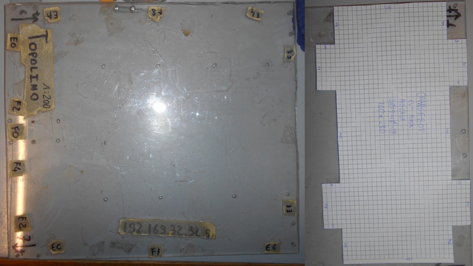

5.3Platform Test

The platform has been enclosed in the mock-up cover and a test has been run to try each motor at full command in both directions individually.

Illustration 9: Full Test
The drivers are left free wheeling when at zero PWM in Option 1 connection. Not a problem, as a closed loop PID will ensure target speed is enforced.


Video 1: Full Test


6Conclusions

This test successfully demonstrated the feasibility of the overall architecture and power train design of the OrangeBot robot due to compete in the PiWars 2020.
Next steps for hardware development are:
  • Connect the Raspberry Pi to the power train electronics
  • Test bidirectional communication between RPI and prototype electronics
  • Test remote control capabilities from the FPV framework already in use inside “Seeker Of Ways B” and “Maze Runner”
  • Rewire the quadrature encoders on board the IG32-05 to the electronics. Test them
  • Test the current sense capabilities of the VNH7040 drivers
  • Develop a quad high precision dual loop (current/speed) PID controller
  • Design a PCB to integrate all the above functionalities


2019-10-29

2019-10-28 OrangeBot Mockup


>>>Mockup<<<


1Mechanical Structure Mockup

With the arrival of the motors, wheels, mounting brackets and hubs, the mechanical construction can begin.
Guiding principle for the construction is the MVP strategy, in which a minimal working version, a vertical slice is built first. Functionalities are added as testing of more basic functionalities is successful.
Objective is to build the minimal structure that demonstrate the mechanical layout of four independent traction wheel with the intended form factor to comply with the Pi Wars 2020 specifications.


2Specifications

Maximum Footprint Width x Length x Height
  • 225mm x 300mm x 370mm Core platform
  • 225mm x 400mm x 450mm With challenge specific attachments
  • 325mm x 500mm x 450mm With extensible flaps

Illustration 1: PiWars Size Specifications

2.1Motor Block Components

Component chosen for the Motor Block are:
Illustration 2: OrangeBot Motor Block Components

Illustration 3: OrangeBot Motor Block Mechanical Drawings
Both the Hub and the wheels needs to be modified to fit the motor block.


2.2Layout

OrangeBot is going to use four independent DC gearmotors with wheels. A central joint is going to allow the platform to swivel around the longitudinal axis of the robot.

Illustration 4: OrangeBot Motor Block Mechanical Drawings


3Mechanical Construction

This section details the manufacturing steps for the mechanical construction.

3.1Motor Block Assembly

First step is to modify the hub and the wheel to fit the motor block.
The motor 6mm shaft already fits the 6mm hub hole.
The wheel must be modified to fit the hub. This requires enlarging the central hole to 12mm.


Video 1: Enlarge wheel hole to 12mm

Next step is to drill through both the hub imperial satellite holes and the wheel to create three M3.5 through hole to fix the wheel to the hub.


Video 2: Satellite M3.5 satellite holes
This process is repeated for all four wheels.


3.2Robot Base MVP

The minimal workable base is a simple slice of acrylic cut to shape and drilled to host the four motor block assemblies. This MVP is meant to demonstrate the traction and electronics and allow to get a feel for the size, in preparation for the next step of the mechanical assembly.

3.2.1Cut Mask

First step is to design the cut mask to accommodate the four motor blocks. The encasing of the encoder of the gearmotors has been removed to save space and because the wirings of the gearmotors are going to be replaced altogether anyway.

Illustration 5: Base MVP Cut Mask


3.2.2Acrylic Sheet

For the sheet of acrylic, the upper plate of our previous robot 'Topolino' was used. The cut mask is kept in place by a few stripes of black tape.

Illustration 6: Acrylic


3.2.3Cut Acrylic Sheet

Using a vertical saw, the acrylic is cut to shape.

Illustration 7: Cut acrylic


3.2.4Acrylic Robot Base

The result is the simplest possible support for the motors.

Illustration 8: Acrylic Robot Base


3.3Motor Mounting Brackets

Now the mounting brackets can be assembled on the robot base.

3.3.1Sanity Check Size

Check that motor block assemblies comply with the PiWars specifications with some margin.
Margin is an healthy 30 x 20 mm.

Illustration 9: Check Size


3.3.2Place Motor Brackets

Mpounting brackets for the motor are placed precisely along guide lines and held in place.

Illustration 10: Place Brackets


3.3.3M3 Drills

M3 holes are drilled as precisely as possible. M3 bolts are used to keep the bracket in place as new holes are drilled.

Illustration 11: Drill acrylic sheet


3.3.4Clean Drills

Clean up the holes and apply M3 bolts to keep brackets in place.

Illustration 12: Countersink and clean up holes


3.3.5Assembly Bracket

The brackets are all assembled and aligned. Now the motors can be attached as well.

Illustration 13: Assembly Motor Brackets


3.4Assembly Motor Blocks

With the mounting brackets and the motors assembled, now the hub wheel assembly can proceed.

Illustration 14: Motors Assembled


3.5Assembly Wheels

Order of assembly:
  1. Insert the M3 wheel screws in the hub (without the wheel)
  2. Insert the hub on the axle and tighten the hub-axle screws.
  3. Insert the wheel.
  4. Tighten the M3 bolt

Illustration 15: Wheel and Hub before and after Drill

Illustration 16: Before and After Drill
It's very tricky to tighten the M3 screws on the wheel.


4Skin Mockup

Cardboard plates were used to prototype the outer structure of the OrangeBot platform. M3x10 screws were used to bolt the plates together, resulting in a surprisingly solid and rigid structure.

Illustration 17: OrangeBot Mockup
The platform is modelled after an Armoured Personal Carrier or APC. The platform is going to feature a fully operational turret, tentatively equipped with an RC grade BB gun emplacement. Tentatively, the turret is going to achieve full 360° turn capabilities and +/-15° of azimuth. The camera is going to be mounted on the gun emplacement for targeting and navigation.

5Conclusions

This document detailed the development of the simplest possible vertical slice for the mechanical assembly.

Illustration 18: OrangeBot Mechanical MVP
ToDo list:
  • Thread the holes on the hub to M4 for ease of assembly
  • Design a base to accommodate the longitudinal joint
  • Design the turret and the chassis