2020-08-08

2020-08-08 Longan Nano GD32VF103 Demo


>>>Longan Nano GD32VF103<<<

Longan Nano GD32VF103 Risc-V 108MHz 32b MCU toolchain, libraries and applications

>>>Longan Nano Demo<<<


Display Class: Interfaces with the ST7735 80x160 display using SPI0 and DMA0.
Screen Class: Provides asynchronous methods to print on the display


1Longan nano GD32VF103 Demo

I built Display, Screen and Chrono class drivers for the Longan nano GD32VF103 board.

This Demo application is meant to show off the features of the drivers and jump start the development of the application.

I spent extra effort in testing and documentation to make sure the drivers are as stable as possible since they are going to be the building blocks for all my future applications on this board.


1.1Chrono Class Driver

The Chrono class uses the 64bit 27MHz@108MHz CPU clock timer to provide accurate timings.

Time units are defined in the Longan_nano::Chrono::Unit enum.

The Chrono class has two modes of operation:

  • start/stop elapsed timer: measures DeltaT

  • start/accumulate: integrate a DeltaT on an accumulator

Those two modes of operations can be used to profile uptime, elapsed time, time spent running code and more.


1.2Display Class Driver

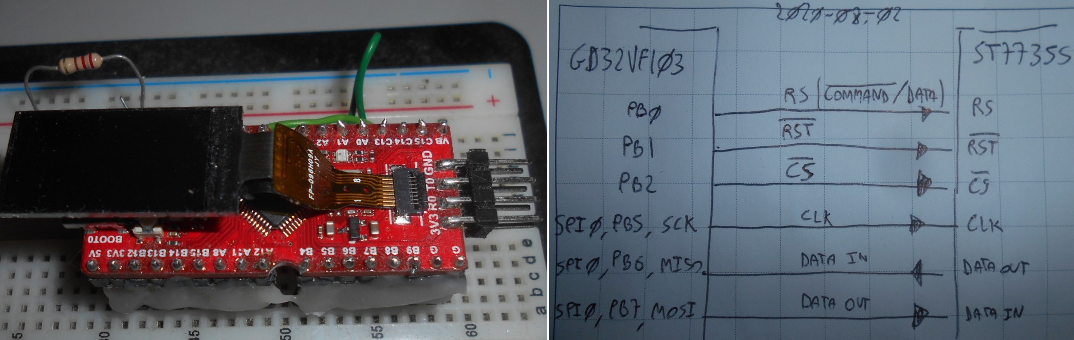
The Display class interfaces directly with the LH096T ST7735S 0.96 inches 80x160 oled color screen.

The library uses the .init method to initialize the display has two modes of operations:

  • register_sprite/update for asynchronous non blocking operations.

  • draw_sprite for synchronous blocking operations.

The Display class uses optional DMA acceleration and the SPI0 and a few GPIOs to communicate with the physical screen.

The Display class does not use interrupts. While using interrupts can make the driver transparent to the user by automagically calling the update method, it can interfere with other real time operations. As design philosophy, the driver is meant to be secondary to the application and meant to show information, giving the application control over the amount of resources used by deciding the call speed of the update method. Calling .update() every 100us will result in about 1250 sprites updated per second. If the user makes more print calls than what the display can handle, the display will simply ignore older calls displaying the most recent sprite. At top load a refresh rate of about 1250/100=12.5 frames per seconds can be expected. The refresh rate becomes 1.25 fps at full load if .update() is executed every 1000us instead of 100us.


1.3Screen Class Driver

The scope of the screen class is to support ascii print of fixed size on fixed grid, and is meant for the common use case of showing debug and runtime number of the application.

The Screen class add a sprite based abstraction layer with print to reduce the size of the frame buffer and CPU use. It also provides a large number of overloaded print methods. The Screen class inherit the Display class, allowing to decouple the physical screen from the print implementation and simplify a move to a bigger screen if needed.

The Screen class supports two ascii fonts. 8x10 Courier Now and 8x16 NSimSum that can be toggled by setting the define FONT_HEIGHT and recompiling, the smaller font shows 8x20=160 sprites on screen, while the bigger font shows 5x20=100 sprites on screen and is easier to read.
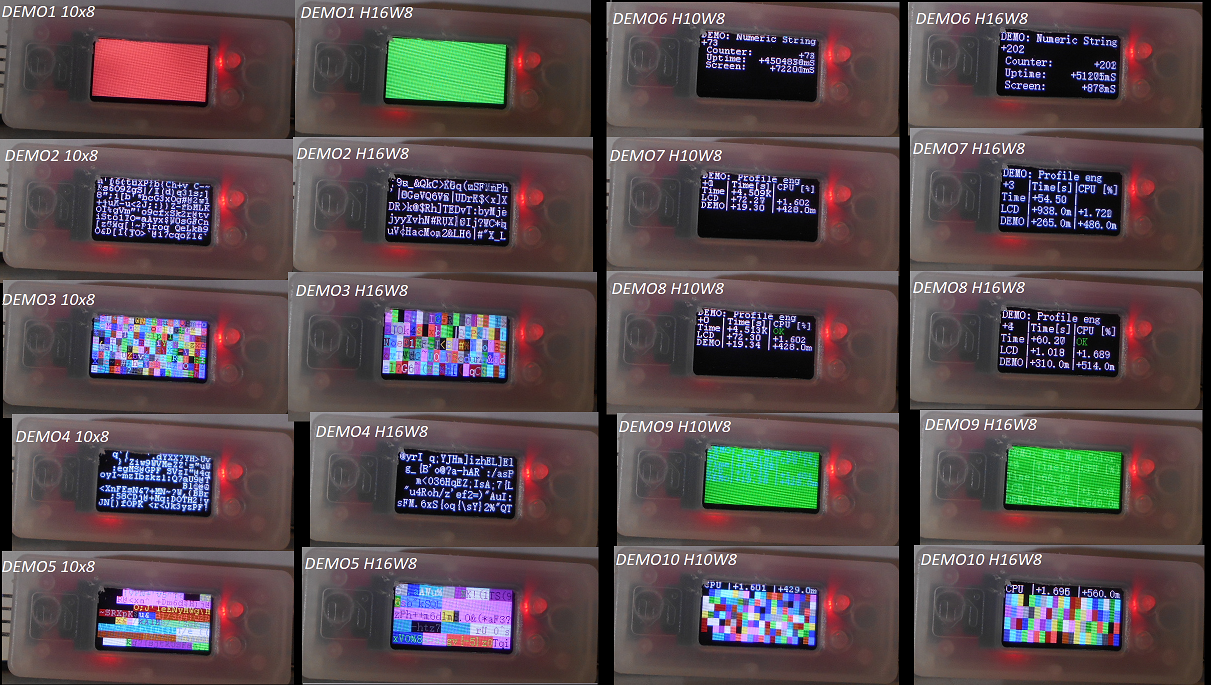

2DEMOS

There are ten demo, showcasing the use of the print and timing functions to display an HMI.

  1. Clear the screen to a random color every 500ms

  2. Print a random character in a random position of the screen every 1ms

  3. Same as above but with random foreground and background colors

  4. Print a random string in a random position of the screen every 25ms

  5. Same as above but with random foreground and background colors

  6. Print numbers with right and left adjust

  7. CPU execution and uptime with engineering format 4 significant digit and SI suffix

  8. Same as above but with screen builtin pending and error methods

  9. Same as above but with random foreground and background colors

  10. Constant workload demo. Print 10 sprites every 25ms and show CPU use

Illustration 1 - Demo


Video 1 - Demo

3Documentation and Style

I made a point to learn more C++ features, with this project I elected to use .hpp files with header and implementation together since inline needs to be declared alongside the header anyway. I also experimented with scoping of typedef and enum to allow the same enum name to be in multiple libraries without conflicts.

I also integrated the Doxygen documentation style comments and generated the automatic documentation, as well as integrating the documentation alongside the code repository in GitHub.

The same style is going to be used for my next classes and drivers.


4Conclusions

I begun this project to learn a Risc-V MCU. The Longan Nano Demo provides an example application for the scheduler, Chrono, Screen and PA8 button, and can be used as a base to develop applications with the Longan Nano GD32VF103.

I am satisfied with the performance, and how the drivers have turned out. The board provides great value, and in my opinion is held back by the poor examples. Hopefully more people will adopt the Longan Nano and help in building libraries and example code to make it easier to develop applications on Risc-V MCUs to come.

The first application of this MCU will be as new motor controller for OrangeBot.


5Source Code

>>>GitHub Repository<<<


5.1Doxygen Documentation

>>>DoxyGen<<<


5.2Source Code

>>>Screen and Display classes<<<


2020-08-03

2020-08-02 Longan Nano GD32vf103 Display and Screen Classes

>>>Longan Nano GD32VF103<<<

Longan Nano GD32VF103 Risc-V 108MHz 32b MCU toolchain, libraries and applications

>>>Longan Nano Screen and Display Classes<<<


Display Class: Interfaces with the ST7735 80x160 display using SPI0 and DMA0.
Screen Class: Provides asynchronous methods to print on the display


1Longan Nano GD32VF103 Display and Screen Classes

The Longan Nano is equipped with an OLED 0.96 inches 80x160 color screen interfaced to the GD32VF103 through the SPI0 peripheral. Additional GPIO pins are used for chip select, reset and data/command mode.

The scope of this document is to explain the design decision, constraints and architectural choices behind the Screen and Display classes that control the display.


2Pin Configuration

The Screen uses a ST7735S controller. The screen is interfaced directly with the microcontroller.

Illustration 1: Schematics

The CS pin unfortunately is not the SPI0 CS, so cannot be generated by hardware and must be controlled via software.

The RS pin as well must be toggled quite often. The SS7735S has a communication protocol in which a command byte is followed by a number of data bytes. In a typical draw operation there are at least four commands to be sent, requiring at least four toggles.


2.1MCU Peripherals

The GD32VF103 is equipped with two majestic DMA controllers for a total of twelve channels.

To minimize CPU use I can use the DMA0 to handle multi byte transfers from memory to the SPI0 peripheral, making the job of transferring pixel data that much cheaper for the CPU.

All of the DMA channels can steal up to 50% of the CPU main bus bandwidth, so some performance degradation can be expected on the CPU.


Illustration 2: GD32VF103 Peripherals


2.2Screen Configuration

The screen uses a 16bit RGB565 color space with 80x160 = 12800 pixels.

SPI0 has been tested up to 6.7MHz of speed.

Others modes are available but would take time to develop and not offer much savings. Current Screen and Display classes are good enough.


3Software Architecture

A lot of effort went into the design of the software, partitioning the workload and in deciding the ABI and HAL structures.


3.1Specifications

First thing to do is to understand my use case and what I want out of the Longan Nano screen.

  • Debug and profiling: Show things like voltages, currents, encoder readings, communication and errors.

  • Mostly ASCII characters: A fancy real time chart would be cool, but a waste of performance. I have the Raspberry Pi if I want to show fancy charts, and have more pixels and cpu to do so.

  • Low CPU and Memory footprint: I need the MCU to perform a fixed function. That's its primary objective. Debug and profile helps out and is secondary.


3.2Bandwidth and Memory Considerations

In order to refresh each pixel I need at minimum a 80x160x2x8=204.800 [Kb] transfer which yield a theoretical maximum of 32.8 [FPS], but would require the CPU to do nothing but line up bytes for the screen considering the prep time.

Any meaningful implementation needs a frame buffer, that for a full screen would be: 80x160x2 = 25.6 [KB] on an available memory of 32 [KB] meaning at minimum I would consume 80% of the working memory just for the screen.


3.3Architecture

I made a sprite based library. This means that the screen only need a frame buffer as big as the biggest sprite.

I partition the driver in two:

  • Display Class: HAL and interface with the physical OLED. Provides sprite draw methods.

  • Screen Class: I abstract one level up and build all my sprite methods in a Screen class. All the print, sprite maps, frame buffer, etc... So if I change display, I can reuse the screen class.

The division means that I have two frame buffers. A frame buffer for the sprites that has the size of the number of sprites that can be drawn on the screen, and a frame buffer for the pixel data of a single sprite that is used for drawing.

Imagining a screen size of 80x160 and a sprite size of 16x8, this mean the frame buffer for the pixel data will be 16x8x2 = 256[B] while the frame buffer for the sprites will be 80/16x160/8 = 100 [B]. A massive saving in memory. Since I need to only show ascii characters anyway, this is not even limiting the flexibility of the draw too much. A drawback is that character are in a fixed grid, instead of being printable in each position.

The SPI needs time to send data, I can make the class asynchronous by returning after initiating the communication. I construct a core Update() method that returns without doing anything if the peripherals are busy.

This architectural decision means that the user will have to periodically call the update method, and it also means that the user decides how much resources allocate to the screen. If the user calls the update method slower than they are calling the print methods, simply some sprites won't be drawn.

Finally, I decide to split the update method in two. The Display::Update() is busy while sending a sprite, and idle otherwise. The higher Screen::Update() scans the frame buffer and register a sprite to send, then loops around the Display::Update() until the draw is complete. Since they are all non blocking calls, this reduces the CPU use to the minimum.

Another optimization is to have an update flag. Sprites are only redrawn if they have changed. This optimization costs an additional update frame buffer, but massively reduces bandwidth use when characters change sparsely.

Illustration 3: Display and Screen Class Architectures


4Conclusions

The Screen Class and Display class provide a ascii based frame buffer and support asynchronous control of the screen on board the Longan Nano board.

Extensive print methods allow to format numbers in a variety of ways for the library primary propose, which is to show fast updating debug information while using little CPU.

No graphics mode is supported as of now.

Future developments include:

  • Reduce idle use by using a pending counter

  • Improve the FSM of the display

  • Improve CPU use


5Source Code

Source code of the Demo application. Repository.


2020-08-02

2020-07-31 Longan Nano GD32VF103 Chrono Class and Scheduler

>>>Longan Nano GD32VF103<<<

Longan Nano GD32VF103 Risc-V 108MHz 32b MCU toolchain, libraries and applications

>>>Longan Nano Chrono Class and Scheduler<<<


Chrono C++ Class uses the 64bit 27MHz systick timer to provide high resolution elapsed time and eaccumulate time HAL methods.

The Demo shows how to implement a fixed function scheduler with overrun and profiling using the Chrono C++ Class.


1Introduction

I use microcontrollers to perform fixed hard real time functions, in which a given list of tasks are executed always at the same rate in the same order, with little variation due to communication with the master.

With the AT4809 and previous microcontroller, I used an internal timer to issue the fast tick as an interrupt service routine, and from that tick, generate all the flags to execute slower tasks.

E.G. The PID running at 4KHz started by a fast tick at 4KHz, the LED running at 2Hz started by prescaling the 4KHz fast tick by 2000.

Illustration 1: Fast Tick issue execution of fixed tasks

With the Longan Nano I have a 64bit 27MHz fast tick timer at my disposal.


2Chrono Class

I decided to create an abstraction layer in class form since I'm practising with C++.

The class embeds two high resolution 64 bit timestamps.

The class uses scoped enums to encapsulate the configurations and definitions inside the namespace and class name e.g. the time unit is: Longan_nano::Chrono::Unit::microseconds


2.1Time Elapsed Mode

One of the core function of the class is to compute how much time has elapsed between two instants of time.

Use:

  • A timer has to be instantiated. Longan_nano::Chrono my_timer;

  • my_timer.start() followed by my_timer.stop() fill the timestamps. my_timer.get_elapsed( Unit ) returns the DeltaT between stop and start

  • my_timer.start() followed by my_timer.stop( Unit ) returns the DeltaT between stop and start


2.2Time Accumulation mode

Another thing the user may want to do is to integrate the time spent doing something to profile execution times or measure something happening in bursts.

The accumulation method has a special flag to use the internal 64 bit timestamps to do this integration at full sub microsecond resolution. This is much better than having the user integrate the rounded results of the elapsed time by hand.

NOTE: the 64bit operation needs a libc call. Use -fno-exceptions compile flag to avoid code size to blow up by 30KB for no reason.

Use:

  • A timer has to be instantiated. Longan_nano::Chrono my_timer;

  • my_timer.start() followed by my_timer.accumulate() fill the timestamps. my_timer.get_accumulator( Unit ) returns all the sum of all DeltaT occurred between start and accumulate

  • my_timer.start() followed by my_timer.accumulate ( Unit ) returns all the sum of all DeltaT occurred between start and accumulate


2.3Chrono Class Source Code


3Demo

This demo shows a practical implementation of an hardwired scheduler that issue the toggle of the RED led at 250mS, and the GREEN led at 750ms, by prescaling the fast tick for the RED led.

This scheduler monitors the overrun of tasks, and light a blue led if error occurs.


Illustration 2: Demo Tasks


Video 1: Demo Tasks


3.1Demo Source Code

Code for the demo to shows the hardwired scheduler, the prescaler, the overrun detection, the uptime measurement and the cpu time measurement.


4Conclusions

Time measurement and scheduling are fundamental to the operation of a fixed function hard real time microcontroller application.

In this document I laid out my solution and my implementation in the form of the Chrono class and fixed scheduler with execution flags. This solution does not use timer peripherals inside the microcontroller, perform unit conversion and works at full resolution and using C++ constructs.

This architecture will serve as the basis for all my applications based on the Longan nano GD32VF103.


2020-07-06 Longan Nano GD32VF103 PA8 and RTC Interrupts

>>>Longan Nano GD32VF103<<<

Longan Nano GD32VF103 Risc-V 108MHz 32b MCU toolchain, libraries and applications


Illustration 1: Longan Nano test bench


1Introduction

The blink example went up quite painlessly, and I was also able to compile and execute the Bad Apple example that takes a stream of bitmap images from the SD Card and shows them on the screen.

With the basics out of the way, I focused on the interrupts.


1.1Arduino Framework Compatibility

The product page claims compatibility with the Arduino Framework, so I wanted to try the Arduino like interrupt handling.

Early on it was obvious that the Arduino framework has not been completed as the time of writing, with basic HAL functions like the digitalRead() empty. There was no hope of getting Arduino style interrupts to work without doing the framework HAL myself, so I dropped the thing.


2Interrupts

The Risc-V ISA specifies the interrupt handling as part of the core. Details about the ECLIC can be found in this excellent post from Kevin Sangeelee.

The GD32VF103 support an interrupt vector table defined as weak symbols in Start.S in the GD32 framework, it supports tiered priority where high priority interrupts can interrupt low priority ones and has hardware acceleration for them inside the MCU, on top of the special instructions and registers inside the core, as per Risc-V ISA specifications.

The GD32VF103 provides special interrupts from all sort of sources, including a reset vector, an error vector and a watchdog vector, on top of interrupts from almost every peripheral.


2.1Difficulties

Getting the interrupts to work was not easy.

In theory, all I had to do was to define a function with the same name as the symbol in start.S, and the C++ linker should have automagically linked the definitions by overriding the default .weak symbols.

After lots of testing, stack overflow came through with the answer: I need to use the keyword extern “C” to tell the C++ compiler not to change the name of the function and allow the linker to do its job and link the address of the interrupt service routine to the interrupt vector table.


3Example: PA8 EXTI

The Boot button is also wired to the PA8 pin. The EXTI in combination with the ECLIC is used to sense an edge on PA8 and trigger an ISR.


Video1: PA8 interrupt demo in action

4Example: RTC Interrupt

The RTC timer is initialized to emit a “second” interrupt every 250ms. The interrupt toggles the RED LED.


5Conclusions

Interrupts are fundamental in an hard real time MCU application and the GD32VF103 is equipped with a refined system to handle interrupts.

This document shows how to generate interrupts from the EXTI and RTC. interrupts can be generated from all sort of sources, and there are even sources for reset, watchdog, errors, etc...