With the electronics and software framework at a good point, next step for
robotic development is to experiment with some AI. Three options were
considered:
Nvidia produced an OS image to integrate their CUDA cores, the Jatson Nano
board and ROS into an AI robot. The choice was made to obtain a Jetson Nano
2GB
The scope of this post is to power up the Jetson Nano and test the basic
configuration procedure, compatibility with the camera module and the
TPS55386 voltage regulators
developed for my robots.
LEGO Technic allows to build mechanical structures, With LEGO I'm limited by
the actuators.
Servo motors are easy to drive and interface with custom electronics.
The scope of the Unit Zero project is to build a quadruped robot using LEGO
Technic for the mechanical construction and using Servo motors and custom
electronics to power the robot.
Display Class: Interfaces with the ST7735 80x160 display using SPI0 and DMA0.
Screen Class: Provides asynchronous methods to print on the display
1Longan
nano GD32VF103 Demo
I built Display, Screen and Chrono class drivers for the Longan
nano GD32VF103 board.
This Demo application is meant to show off the features of the
drivers and jump start the development of the application.
I spent extra effort in testing and documentation to make sure the
drivers are as stable as possible since they are going to be the
building blocks for all my future applications on this board.
1.1Chrono
Class Driver
The Chrono class uses the 64bit 27MHz@108MHz CPU clock timer to
provide accurate timings.
Time units are defined in the Longan_nano::Chrono::Unit enum.
The Chrono class has two modes of operation:
start/stop elapsed timer: measures DeltaT
start/accumulate: integrate a DeltaT on an accumulator
Those two modes of operations can be used to profile uptime,
elapsed time, time spent running code and more.
The library uses the .init method to initialize the display has
two modes of operations:
register_sprite/update for asynchronous non blocking
operations.
draw_sprite for synchronous blocking operations.
The Display class uses optional DMA acceleration and the SPI0 and
a few GPIOs to communicate with the physical screen.
The Display class does not use interrupts. While using interrupts
can make the driver transparent to the user by automagically calling
the update method, it can interfere with other real time operations.
As design philosophy, the driver is meant to be secondary to the
application and meant to show information, giving the application
control over the amount of resources used by deciding the call speed
of the update method. Calling .update() every 100us will result in
about 1250 sprites updated per second. If the user makes more print
calls than what the display can handle, the display will simply
ignore older calls displaying the most recent sprite. At top load a
refresh rate of about 1250/100=12.5 frames per seconds can be
expected. The refresh rate becomes 1.25 fps at full load if .update()
is executed every 1000us instead of 100us.
1.3Screen
Class Driver
The scope of the screen class is to support ascii print of fixed
size on fixed grid, and is meant for the common use case of showing
debug and runtime number of the application.
The Screen class add a sprite based abstraction layer with print
to reduce the size of the frame buffer and CPU use. It also provides
a large number of overloaded print methods. The Screen class inherit
the Display class, allowing to decouple the physical screen from the
print implementation and simplify a move to a bigger screen if
needed.
The Screen class supports two ascii fonts. 8x10 Courier Now and
8x16 NSimSum that can be toggled by setting the define FONT_HEIGHT
and recompiling, the smaller font shows 8x20=160 sprites on screen,
while the bigger font shows 5x20=100 sprites on screen and is easier
to read.
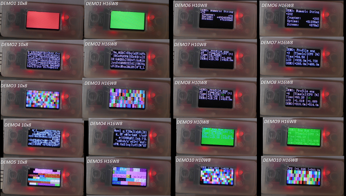
2DEMOS
There are ten demo, showcasing the use of the print and timing
functions to display an HMI.
Clear the screen to a random color every 500ms
Print a random character in a random position of the screen
every 1ms
Same as above but with random foreground and background
colors
Print a random string in a random position of the screen
every 25ms
Same as above but with random foreground and background
colors
Print numbers with right and left adjust
CPU execution and uptime with engineering format 4
significant digit and SI suffix
Same as above but with screen builtin pending and error
methods
Same as above but with random foreground and background
colors
Constant workload demo. Print 10 sprites every 25ms and show
CPU use
Illustration 1 - Demo
Video 1 - Demo
3Documentation and Style
I made a point to learn more C++ features, with this project I
elected to use .hpp files with header and implementation together
since inline needs to be declared alongside the header anyway. I also
experimented with scoping of typedef and enum to allow the same enum
name to be in multiple libraries without conflicts.
I also integrated the Doxygen documentation style comments and
generated the automatic documentation, as well as integrating the
documentation alongside the code repository in GitHub.
The same style is going to be used for my next classes and
drivers.
4Conclusions
I begun this project to learn a Risc-V MCU. The Longan Nano Demo
provides an example application for the scheduler, Chrono, Screen and
PA8 button, and can be used as a base to develop applications with
the Longan Nano GD32VF103.
I am satisfied with the performance, and how the drivers have
turned out. The board provides great value, and in my opinion is held
back by the poor examples. Hopefully more people will adopt the
Longan Nano and help in building libraries and example code to make
it easier to develop applications on Risc-V MCUs to come.
The first application of this MCU will be as new motor controller
for OrangeBot.
Display Class: Interfaces with the ST7735 80x160 display using SPI0 and DMA0.
Screen Class: Provides asynchronous methods to print on the display
1Longan
Nano GD32VF103 Display and Screen Classes
The Longan Nano is equipped with an OLED 0.96 inches 80x160 color
screen interfaced to the GD32VF103 through the SPI0 peripheral.
Additional GPIO pins are used for chip select, reset and data/command
mode.
The scope of this document is to explain the design decision,
constraints and architectural choices behind the Screen and Display classes that control the display.
2Pin Configuration
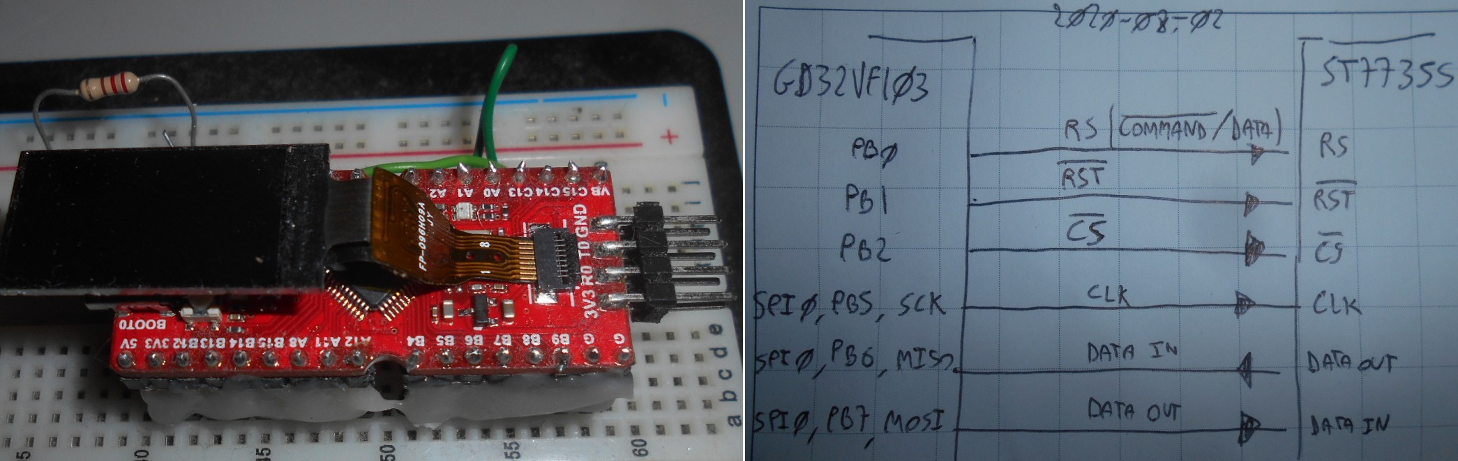
The Screen uses a ST7735S controller. The screen is interfaced
directly with the microcontroller.
Illustration 1: Schematics
The CS pin unfortunately is not the SPI0 CS, so cannot be
generated by hardware and must be controlled via software.
The RS pin as well must be toggled quite often. The SS7735S has a
communication protocol in which a command byte is followed by a
number of data bytes. In a typical draw operation there are at least
four commands to be sent, requiring at least four toggles.
2.1MCU
Peripherals
The GD32VF103 is equipped with two majestic DMA controllers for a
total of twelve channels.
To minimize CPU use I can use the DMA0 to handle multi byte
transfers from memory to the SPI0 peripheral, making the job of
transferring pixel data that much cheaper for the CPU.
All of the DMA channels can steal up to 50% of the CPU main bus
bandwidth, so some performance degradation can be expected on the
CPU.
Illustration 2: GD32VF103 Peripherals
2.2Screen
Configuration
The screen uses a 16bit RGB565 color space with 80x160 = 12800
pixels.
SPI0 has been tested up to 6.7MHz of speed.
Others modes are available but would take time to develop and not
offer much savings. Current Screen and Display classes are good
enough.
3Software Architecture
A lot of effort went into the design of the software, partitioning
the workload and in deciding the ABI and HAL structures.
3.1Specifications
First thing to do is to understand my use case and what I want out
of the Longan Nano screen.
Debug and profiling: Show things like voltages, currents,
encoder readings, communication and errors.
Mostly ASCII characters: A fancy real time chart would be
cool, but a waste of performance. I have the Raspberry Pi if I want
to show fancy charts, and have more pixels and cpu to do so.
Low CPU and Memory footprint: I need the MCU to perform a
fixed function. That's its primary objective. Debug and profile
helps out and is secondary.
3.2Bandwidth
and Memory Considerations
In order to refresh each pixel I need at minimum a
80x160x2x8=204.800 [Kb] transfer which yield a theoretical maximum of
32.8 [FPS], but would require the CPU to do nothing but line up bytes
for the screen considering the prep time.
Any meaningful implementation needs a frame buffer, that for a
full screen would be: 80x160x2 = 25.6 [KB] on an available memory of
32 [KB] meaning at minimum I would consume 80% of the working memory
just for the screen.
3.3Architecture
I made a sprite based library. This means that the screen only
need a frame buffer as big as the biggest sprite.
I partition the driver in two:
Display Class: HAL and interface with the physical OLED.
Provides sprite draw methods.
Screen Class: I abstract one level up and build all my sprite
methods in a Screen class. All the print, sprite maps, frame buffer,
etc... So if I change display, I can reuse the screen class.
The division means that I have two frame buffers. A frame buffer
for the sprites that has the size of the number of sprites that can
be drawn on the screen, and a frame buffer for the pixel data of a
single sprite that is used for drawing.
Imagining a screen size of 80x160 and a sprite size of 16x8, this
mean the frame buffer for the pixel data will be 16x8x2 = 256[B]
while the frame buffer for the sprites will be 80/16x160/8 = 100 [B].
A massive saving in memory. Since I need to only show ascii
characters anyway, this is not even limiting the flexibility of the
draw too much. A drawback is that character are in a fixed grid,
instead of being printable in each position.
The SPI needs time to send data, I can make the class asynchronous
by returning after initiating the communication. I construct a core
Update() method that returns without doing anything if the
peripherals are busy.
This architectural decision means that the user will have to
periodically call the update method, and it also means that the user
decides how much resources allocate to the screen. If the user calls
the update method slower than they are calling the print methods,
simply some sprites won't be drawn.
Finally, I decide to split the update method in two. The
Display::Update() is busy while sending a sprite, and idle otherwise.
The higher Screen::Update() scans the frame buffer and register a
sprite to send, then loops around the Display::Update() until the
draw is complete. Since they are all non blocking calls, this reduces
the CPU use to the minimum.
Another optimization is to have an update flag. Sprites are only
redrawn if they have changed. This optimization costs an additional
update frame buffer, but massively reduces bandwidth use when
characters change sparsely.
Illustration 3: Display and Screen Class
Architectures
4Conclusions
The Screen Class and Display class provide a ascii based frame
buffer and support asynchronous control of the screen on board the
Longan Nano board.
Extensive print methods allow to format numbers in a variety of
ways for the library primary propose, which is to show fast updating
debug information while using little CPU.
Chrono C++ Class uses the 64bit 27MHz systick timer to provide high resolution elapsed time and eaccumulate time HAL methods.
The Demo shows how to implement a fixed function scheduler with overrun and profiling using the Chrono C++ Class.
1Introduction
I use microcontrollers to perform fixed hard real time functions,
in which a given list of tasks are executed always at the same rate
in the same order, with little variation due to communication with
the master.
With the AT4809 and previous microcontroller, I used an internal
timer to issue the fast tick as an interrupt service routine, and
from that tick, generate all the flags to execute slower tasks.
E.G. The PID running at 4KHz started by a fast tick at 4KHz, the
LED running at 2Hz started by prescaling the 4KHz fast tick by 2000.
Illustration 1: Fast Tick issue execution of fixed
tasks
With the Longan Nano I have a 64bit 27MHz fast tick timer at my
disposal.
2Chrono Class
I decided to create an abstraction layer in class form since I'm
practising with C++.
The class embeds two high resolution 64 bit timestamps.
The class uses scoped enums to encapsulate the configurations and
definitions inside the namespace and class name e.g. the time unit
is: Longan_nano::Chrono::Unit::microseconds
2.1Time
Elapsed Mode
One of the core function of the class is to compute how much time
has elapsed between two instants of time.
Use:
A timer has to be instantiated. Longan_nano::Chrono
my_timer;
my_timer.start() followed by my_timer.stop() fill the
timestamps. my_timer.get_elapsed( Unit ) returns the DeltaT between
stop and start
my_timer.start() followed by my_timer.stop( Unit ) returns
the DeltaT between stop and start
2.2Time
Accumulation mode
Another thing the user may want to do is to integrate the time
spent doing something to profile execution times or measure something
happening in bursts.
The accumulation method has a special flag to use the internal 64
bit timestamps to do this integration at full sub microsecond
resolution. This is much better than having the user integrate the
rounded results of the elapsed time by hand.
NOTE: the 64bit operation needs a libc call. Use
-fno-exceptions compile flag to avoid code size to blow up by 30KB
for no reason.
Use:
A timer has to be instantiated. Longan_nano::Chrono
my_timer;
my_timer.start() followed by my_timer.accumulate() fill the
timestamps. my_timer.get_accumulator( Unit ) returns
all the sum of all DeltaT occurred between start and accumulate
my_timer.start() followed by
my_timer.accumulate ( Unit ) returns all the sum of all DeltaT
occurred between start and accumulate
2.3Chrono Class Source Code
3Demo
This demo shows a practical implementation of an hardwired
scheduler that issue the toggle of the RED led at 250mS, and the
GREEN led at 750ms, by prescaling the fast tick for the RED led.
This scheduler monitors the overrun of tasks, and light a blue led
if error occurs.
Illustration 2: Demo Tasks
Video 1: Demo Tasks
3.1Demo
Source Code
Code for the demo to shows the hardwired scheduler, the prescaler,
the overrun detection, the uptime measurement and the cpu time
measurement.
4Conclusions
Time measurement and scheduling are fundamental to the operation
of a fixed function hard real time microcontroller application.
In this document I laid out my solution and my implementation in
the form of the Chrono class and fixed scheduler with execution
flags. This solution does not use timer peripherals inside the
microcontroller, perform unit conversion and works at full resolution
and using C++ constructs.
This architecture will serve as the basis for all my applications
based on the Longan nano GD32VF103.
The blink example went up quite painlessly, and I was also able to
compile and execute the Bad Apple example that takes a stream of
bitmap images from the SD Card and shows them on the screen.
With the basics out of the way, I focused on the interrupts.
1.1Arduino Framework Compatibility
The product page claims compatibility with the Arduino Framework,
so I wanted to try the Arduino like interrupt handling.
Early on it was obvious that the Arduino framework has not been
completed as the time of writing, with basic HAL functions like the
digitalRead() empty. There was no hope of getting Arduino style
interrupts to work without doing the framework HAL myself, so I
dropped the thing.
2Interrupts
The Risc-V ISA specifies the interrupt handling as part of the
core. Details about the ECLIC can be found in this excellent post
from Kevin Sangeelee.
The GD32VF103 support an interrupt vector table defined as weak
symbols in Start.S in the GD32 framework, it supports tiered priority
where high priority interrupts can interrupt low priority ones and
has hardware acceleration for them inside the MCU, on top of the
special instructions and registers inside the core, as per Risc-V ISA
specifications.
The GD32VF103 provides special interrupts from all sort of
sources, including a reset vector, an error vector and a watchdog
vector, on top of interrupts from almost every peripheral.
2.1Difficulties
Getting the interrupts to work was not easy.
In theory, all I had to do was to define a function with the same
name as the symbol in start.S, and the C++ linker should have
automagically linked the definitions by overriding the default .weak
symbols.
After lots of testing, stack overflow came through with the
answer:
I need to use the keyword extern “C” to tell the C++ compiler not
to change the name of the function and allow the linker to do its job
and link the address of the interrupt service routine to the
interrupt vector table.
3Example: PA8
EXTI
The Boot button is also wired to the PA8 pin. The EXTI in
combination with the ECLIC is used to sense an edge on PA8 and
trigger an ISR.
Video1: PA8 interrupt demo in action
4Example: RTC Interrupt
The RTC timer is initialized to emit a “second” interrupt
every 250ms. The interrupt toggles the RED LED.
5Conclusions
Interrupts are fundamental in an hard real time MCU application
and the GD32VF103 is equipped with a refined system to handle
interrupts.
This document shows how to generate interrupts from the EXTI and
RTC. interrupts can be generated from all sort of sources, and there
are even sources for reset, watchdog, errors, etc...
My big 2019/2020 project, the Pi-Wars, was delayed due to Human
Malware. With an additional year of development I decided to go back
to the drawing board and expand the scope of the platform.
One of the aspects of OrangeBot I wish to improve is the motor
controller. Shortcomings:
CPU: I hit the upper limit of the AT4809 8b
20MHz MCU running two 16b PID controller with two loops each at
2KHz, limiting the precision of the controls.
Current: No current loop in the PID controller.
Adding one promises to optimize performance and efficiency
Auto-Tune: A PID auto-tuning algorithm based on
light machine learning can optimize the precision of the PID. It can
also compensate in runtime for changes in parameters to an extent
(e.g. gearbox getting looser)
Screen: No screen on the motor board to
quickly assess power, position and speed. Even error reporting
relies on either a LED or the webserver. Clunky for debug
The decision was taken to upgrade to a new microcontroller.
1.1Why the Longan Nano GD32VF103
Given the additional time, I was in the mood to learn something
new. Risc-V is gaining in traction, so I searched for a Risc-V based
MCU. The 32b architecture already grant a 2X to 8X improvement to an
8b MCU for fixed point arithmetic, ensuring this would fix the lack
of CPU power.
After some research, I found the Longan
Nano. The performance are amazing for the price:
5$
32b 108 [MHz]
RV32IMAC+ECLIC
80x160 screen
In-circuit programmer
Reset+Button+RGB LED
Timer with quadrature decoder
The price to performance of the platform is AMAZING, and the
feature set allows for everything I need to include in the motor
controller.
One of four advanced timers allow to decode in hardware the
encoder reading, without relying on costly ISR decoding, I have ADC
channels for current reading, DMA, communication, and much more.
Adding a screen for 5$ is incredible. They threw in a cheap plastic
case for good measure and a couple of pin strips.
In the end I paid about 10€ per board considering import duty
and delivery.
That's not all. In order for the board to show up, you need to:
Press the boot button (top button)
While boot is pressed, press and release the reset button
Release the boot button
This makes the MCU enter programming mode, allowing it to show up
on the Gigadevice GD32 MCU Tool. Always check verify. The firmware to
be uploaded is the .hex stored in the .pio\build\sipeed-longan-nano
subfolder of the project.
Illustration 3: DFU Firmware Upload tool
I was unable to make DFU
tool work with the one click upload feature of VS Code, but its not a
big deal to upload manually. It might be possible to use the serial
port and a serial port adapter with a bootloader to use that feature,
but I have yet to try, and USB-C is convenient apart from having to
use the button combination to get the board in programming mode.
3.2New Project
With the toolchain in place, its time to start coding. On new
project, you can select folder and framework. Use a custom project
folder and Arduino framework.
Illustration 4: New Project
You have a choice of two framework. The GD32 framework doesn't
work and I was unable to get to work. The Arduino framework can run
the blink example. And nothing else. Even DigitalRead is not coded in
the HAL Arduino library.
What does work is to use the Arduino framework write a main, and
just use the functions in gd32vf103.h.
From here
you can pick my barebone example that should work with interrupts.
From now on, you can compile a project with VS Code and upload
with DFU tool on the Longan Nano board.
4User Library
Like I did for other microcontrollers, I'm going to slowly build
up upon the base HAL to have convenient driver and file structure for
new projects.
I plan to use C++ classes whenever makes sense, and have a basic
IO configuration init procedure and examples for how to do stuffs
right. Lightweight screen drivers, initialize timers in various
modes, hardwired scheduler, etc...
4.1Examples
Unfortunately the Longan Nano has few examples and bad
documentation.
There are examples
for other evaluation boards and GD32 MCUs to help draw the
drivers of the various peripherals, but it takes work to adapt them
and make them work.
The Risc-V has a very refined interrupt controller compared to the
MCU I'm used to. The ECLIC is and extension and part of the Risc-V
instruction set of the MCU. It provides special registers and
instructions.
The ECLIC is interfaced with other controller like the EXTI to
provide an extensive tiered interrupt support. There are also vectors
to handle exceptions, watchdog, etc...
I feel it'll take time to master its use.
5Conclusions
The Longan Nano is a powerful 32b Risc-V MCU that fits the use
case of the OrangeBot control board perfectly. Despite the clunkiness
of the toolchain and lack of documentation, the cost and feature set
provide great value and I consider it a great entry point to learn
32b MCUs and Risc-V.
By design, OrangeBot was meant to be powered by four DC motors and
have a top speed of 20 [Km/h]. Supply shortages meant that the only
motors available were capable of either 10 [Km/h] or 30 [Km/h].
30 [Km/h] motors were ordered and installed, but during the design
stage, the torque needed to turn with a four wheeled platform was not
accounted for. This caused two severe problems:
In order to turn a platform with four fixed wheels, a torque is
required to make the wheels slide on the terrain sideways. It was
impossible to solve this issue even with overvolting the 12 [V] DC
motors, and it was impossible to source new slower stronger motors in
time for the competition. The scope for the platform was reduced, and
OrangeBot is now equipped with two DC Motors and one pivot wheel.
While this allows OrangeBot to turn, the torque was further
halved, impeding acceleration and climbing performance.
1.2Motor
Gain
The motor had too much gain in terms of [mm/s/V]. PWM controls
were unusable, and the PID controller had an impossible job.
Encoders were upgraded from low count magnetic to high count
optical, giving the PID a better chance. After months of work, a two
loop PID controller with integral speed reference running at 2 [KHz]
and consuming all available computational power on the
microcontroller was finally able to suppress ringing and instability
and achieve a controllable platform even under the effect of the
large inertia.
The motors were highly stressed by continuous fine motion
inversion, but the performance were Pi-Wars grade.
2Motor Swap
With additional time, it became possible to just source motors
better tuned to the task.
Illustration 1 - Motor Stats
Original
Motors
The original motors have a speed gain of 613.9 [mm/s/V], a force
gain of 14.04 [g/A] and an encoder scale of 15.79 [cnt/mm] thanks to
the high resolution replacement quadrature optical encoders. Replacement
Motors
The replacement motors have a gain of 185 [mm/s/V], a force gain
of 28.18 [g/A] and an encoder scale of 0.9639 [cnt/mm].
Note that with the original motors, the torque is low enough that
the drag significantly affect top speed. With a drag of 0.001, top
speed is about 32 [Km/h]; With a drag of 0.02 top speed lowers to 15
[Km/h].
2.1Uninstall Motors
Uninstall old motors:
Remove wheels by unscrewing them from the Hub
Remove Hub
Disconnect the power and the encoder wiring from the Main
Motor Board
Unscrew the motor from the motor bracket
Illustration 2 - Uninstall Motors
2.2Uninstall Motor Brackets
The replacement motors are longer. Motor Brackets have to be
uninstalled and new holes have to be made to fix them to the
structure.
Illustration 3 - Interaxis
Interaxis with the original motors was 190 [mm].
The interaxis with the replacement motors is still compatible with
Pi-Wars specifications, but is getting dangerously close to the 225
[mm] limit.
2.3Re-Install Motor Brackets
New holes are made for the M3 bolts that hold the motor brackets
in place.
Illustration 4 - Re-install motor brackets
Due to overlap between old and new holes, the interaxis is not
optimal, and could be reduced from 220 [mm] to 210 [mm]. Doing so
would require redoing the Base Plate upon which the platform is built
upon.
A task for the future might be to cut new plates using a laser
plotter, but for now focus is on achieving the target performance.
Optimization of workable if sub-optimal features will be left for
later.
2.4Install Replacement Motors
Installing the motor is straightforward. The power wiring of the
motors were replaced with higher gauge prior the installation, the
encoder wirings was cut to size in this step.
Illustration 5 - Install Replacement Motors
2.5Solder connectors
Power wirings are soldered with a tip. Encoder wirings are
soldered with an L 2.54 [mm] pin strip. Main
Motor Board
Illustration 6 - Solder motor and encoder
connectors
2.6Assembly
Assembly the hubs, wheels and the platform back together.
Illustration 7- OrangeBot Undercarriage
3Testing and Calibration
3.1Power
Test
The platform powers up without problems
Illustration 8- OrangeBot Powered
3.2PWM Remote Control Test
Test PWM controls. Thanks to the reduced speed and increased
torque, OrangeBot now controls just fine in PWM mode, with the only
drawback of not going in a straight line.
Video 1- OrangeBot PWM Remote Controls
3.3PID
Calibration and PID Remote Control Test
A quick calibration of the PID through the remote controls was
enough to get good closed loop performance and have the platform move
in a straight line.
Illustration 9- PID Calibration
Video 2- Position PID Calibration
4Conclusions
The replacement motors have more torque and less speed, allowing
OrangeBot to be stronger and more precise.
There are other design decisions and mistakes made to achieve the
deadline of 2020-03-29. With the deadline moved to 2021-03, many of
those decisions can be revisited, to achieve an higher quality
design.
With the completion of the high speed controls and low latency
video streaming, the stage is set to proceed with the final phase of
construction of the OrangeBot platform.
This is the biggest upgrade since the construction of the core
platform, and beyond this point only minor adjustments should be
required.
Mechanical upgrades:
Component fitting and Pi-Wars specification check
Turret
Main weapon
Rotation and Elevation mechanism
Attachments:
Pi-Noon Hard Point and Pi-Noon melee weapon servo
Lava Palaveer sensors
Eco Disaster forklift
Battery Strap
Maintenance hatches
Electronics:
Servos: Electronics, connectors, cable management and power
Power: Main switch, distribution, cable management, turret
joint routing
Raspberry-Pi: Power, I2C and UART proto hat
Sensors: I2C network
LED swag!
Firmware:
Servo driver and messages
Main weapon driver and messages
Forklift driver and messages
Pi-Noon lance driver and messages
Software
Key bindings
Integration of all remote controls in the client HMI
1.1Disassembly
The platform was disassembled in preparation for the upgrade.
Illustration 1 - OrangeBot Disassembly
Several plates of the platform needs upgrading, other plates have
now become obsolete and have to be rebuilt to spec to fix fitting
mistakes and support new functionalities.
Electronics need minor modifications and many new cables needs to
be routed.
1.2Obsolete
Plates
The now obsolete “platform top plate”, “turret base plate”
and “turret rear plate” needs retiring as they were place
holders.
Illustration 2 - OrangeBot Retired Plates
2Main Electronics
Main board has to be upgraded to support:
Three servo motors
Switch (Main Weapon Feedback)
Third DC Motor (Main Weapon Spring)
The upgrade is mostly painless, requiring an handful of connectors
and resistors. Testing was done to ensure the board was operational
and would likely not need a second upgrade.
Unfortunately testing revealed that three full sized servos cannot
be powered by the main board and require a second independent 5V3A
power regulator, that was cannibalized from “Maze Runner”.
Illustration 3 - Main Board Upgrade
2.1Main Weapon Test
A key decision for the next phase of component fitting was
whatever the main weapon could be mounted side ways or needed to be
mounted up strainght.
Illustration 4 - Main Weapon Side Loader Test
(FAIL)
The rest revealed that the side loader has reliability issues, and
a top load mechanism is required.
3Turret Construction
With key decisions about the design taken, construction could move
to the next phase.
3.1Turret
Mockup
A Mockup of the turret mechanism was made to take measurements on
the size of various plates and decide on the component placement and
fitting.
Illustration 5 - Turret Mockup
3.2Turret Rotation
With the elevation mechanism and turret dimensions sorted out, it
was time to go back to the original design and evaluate the place
holder rotation mechanism.
The rotation is critical as it has to withstand the inertia and
shock of the moving platform and has to be reliable. After careful
consideration, it was decided to retire the previous mechanism and
redo three plates.
Illustration 6 - Rotation Mechanism Mockup
It became necessary to turn upside down the turret joint to
increase clearance for the rotation servo inside the platform and
inside the turret to increase the range of the elevator mechanism,
also by turning upside down mechanism, the key that connects the
rotation joint with the rotation servo no longer needs a clearance
with the rotation joint walls, increasing significantly the
robustness of the mechanism.
The rotation joint was also moved more toward the rear of the
platform. This has the benefit of looking better (swag first!) and
granting better clearance to both the components inside the platform
and inside the turret.
There were two ways to place the rotation joint. As Murphy
dictates, the wrong way was chosen initially!
3.3“Top Plate” and Rotation Joint
A new top plate was constructed to accommodate the rotation joint
mounted in reverse. The holes to fix the top plate to the platform
were reduced from eight to four, with a fixed bolt and a space below
them. This allows for easier maintenance, as removing four bolts
allow the turret, the top plate and the rotation mechanism to come
off in one piece. An air gap is maintained to get some airflow inside
the platform in case thermals become a concern.
Illustration 7 - Top Plate and Flipped Rotation
Joint
3.4Rotation Mechanism
It was very important to take extra care in the design and
construction of the “Rotation Mechanism” as this servo and joint
have to tank the rotational inertia of the turret caused by the
motion of the platform.
Illustration 8 - Rotation Mechanism
The Rotation Servo is kept in place by a structure below the
turret fixed by long M4x60 bolts.
A “Rotation Key” transmit the motion from the servo, through
the hollow hole of the “Rotation Joint” up to the “Rotation
Plate”. The key itself can be moved upward to disconnect the servo
from the turret quickly for maintenance.
The “Rotation Plate” will feature additional holes for the
cables to pass from the turret to the platform.
3.5Turret Component Fitting
Another critical component of the design is the “Turret Base
Plate”. It's important to get the dimension and placement of the
holes right as all other turret plates and components use this plate
as base.
Illustration 9 - Component Fitting - Second
Iteration
A second round of component fitting was performed to estimate
turret dimensions and placement. In this fitting, it was decided to
move the Raspberry Pi to the “Front Elevator Plate” because of
the convenience of attaching the RaspiCam flat cable. The Elevation
Servo and Elevation Mechanism was also validated in this phase.
Illustration 10 - Turret Plates Masks and Cut
With the dimensions confirmed, the turret plate masks were
prepared, and plates were cut to shape. No holes or other cut out
were made in this phase. This allowed for a third iteration of
component fitting to make sure the plates were cut right
3.6Turret Elevator Plate
Because so much of the fitting depends on the elevator mechanism,
the first turret plate to be finalized was the “Turret Elevator
Plate”.
Illustration 11 - Turret Elevator Plate Components
Fitting
A third iteration of components fitting was performed to decide on
the Elevator Joint and the position of the turret components:
Raspberry Pi
Main Weapon
RaspiCam
Targeting Laser
Elevator Joint
3.7Turret Base Plate
With the design of the turret validated, the Turret Base Plate
could finally be prepared and placed in position. The Rotation Joint
was quickly tested and proved to perform flawlessly, achieving a
great coupling between turret and the rotation servo below.
Illustration 12 - Turret Base Plate
The Rotation Mechanism fits nicely inside the platform with all
other components in place.
Illustration 13 - Rotation Mechanism Fitting
3.8Elevator Joint
The elevator joint is constructed from Lego Technic components and
M3 bolts. Lego makes it much easier to build a rotating connection.
The elevator joint connects the “Turret Elevator Plate” to the
“Turret Right Plate” and “Turret left Plate”.
Illustration 14 - Elevator Joint
The elevator plate is connected to the elevator servo at the
bottom end point. The motion of the plates makes the butt of the main
weapon move up or down. Its limits are the rotation joint and the
turret top plate.
Illustration 15 - Elevator Range
The main weapon is not meant to behave as a mortar or long range
artillery, so the elevator range does not have to be massive.
Something in between 10° of liberty would be more than enough to
aim, even when the robot wants to aim at a ground level target while
climbing a ramp.
The main weapon is connected to the Turret Elevator Plate by means
of an L shaped structural element with two M4 bolts.
3.9Turret
Top and Rear Plates
The Top and Rear plates are straightforward. They just needs holes
for the L shaped structural elements.
Illustration 16 - Turret Top and Rear Plates
3.10Turret Final Assembly
The “Turret Left Plate” was the last to be constructed, and
accommodates the “Elevator Servo”.
The Elevator Servo is connected to the bottom of the “Turret
Elevator Plate” with a beam made from a clips and held in place by
M3 bolts.
Illustration 17 - Final Assembly Side View
Illustration 18 - Final Assembly Top View
The video below shows how the Rotation and Elevator Joints
operate.
Video 1: Rotation and Elevation mechanism
4Conclusions
With the completion of the turret, the platform is finally nearing
completion.
The platform dimensions:
Width: 190 [mm]
Length: 260 [mm]
Height: 310 [mm]
Weight: 3811 [g]